
First published in The International Journal of Hydropower & Dams – Volume Fifteen, Issue 5, 2008
Design of Francis turbine runners based on a surrogate model approach
Ståle Risberg, M. Sc., Spetals Verk AS
Magnus Jonassen, M. Sc., Spetals Verk AS
Roy Jonassen, M. Sc., Spetals Verk AS
Abstract
This paper will demonstrate the use of a surrogate model based approach for Francis turbine runners design. Spetals Verk has taken the benefit from a new parametric definition of the Francis turbine runner blade in combination with extensive and systematic CFD and FEM simulations, and is now implementing a surrogate model approach in their Francis turbine design process. This enables evaluating a large range of factors simultaneously, tuning the surrogate models to mimic the Francis turbine runner responses. The surrogate model is also a useful way to gain insight into the global behavior of various runner profiles.
A complete new design series of Common Blade™ Francis runners are under development based on this approach. The Common Blade™ name reflects that the same parametric blade description, in combination with systematic CFD and FEM simulations, is utilized in all projects. This ensures a systematic and continuous philosophy – optimizing the runner profiles according to the actual flow and head given by the nature in each specific project.
Introduction
One of the major challenges in hydro turbine design is to ensure a globally optimized design, taking into account the many responses of the turbine design such as performance at various operating points, cavitation, operating stresses, pressure pulsations, weight, size, fatigue life, vibration and manufacturability. Also, hydraulic interaction between the turbine components needs to be addressed, to ensure a globally optimized turbine design. Not only are there a large number of responses, but also the designer needs to consider these responses simultaneously. For example, a designer typically wants to increase efficiency without increasing operating stresses. Optimal settings of the design parameters for one response may be far from optimal, or even physically impossible, for another. In addition, the runner blades are geometrically complex and their shape is typically controlled by a large number of design parameters. Traditionally, the optimization of a turbine design involves setting the design parameters so that the result becomes as good as possible. Often this is done by changing one design parameter at a time, until no further improvement is achieved. This approach is normally denoted as the COST approach (Changing One Separate parameter at a Time) and is recognized to be very time consuming, even for an experienced designer. Focusing on few responses and/or design parameters at the time could also prevent insight into possible relationships between the various responses and design parameters. This approach could thus lead to a sub-optimized turbine design, or at worst, a turbine failing to meet its expectation on site.
Recent trends
Currently, hydro turbine designers rely to a large extent on simplified CFD solvers (typically 3D Euler or potential flow solvers) to reduce the CPU time needed for the optimization. These codes typically lack some accuracy in terms of performance predictions compared with the fully 3D Navier-Stokes solvers, especially far from best efficiency operation where turbulent flow is more dominant. Fully 3D Navier-Stokes solvers, which also include turbulence modelling, are mainly used in the final stage of the optimization for fine-tuning and verification. The optimization process is also usually manually driven, meaning that the designer is changing the geometry based on the previous simulation results. The final turbine design is therefore, to a large extent, reflecting the specific designer’s personal experience.
During the last decade, a dramatic increase in computational force has been experienced. Even simulations which a few years ago were only realistic on specialized, and expensive, simulation computers are now carried out on standard personal computers. Also, the communication between various commercial CFD/FEM codes, meshing codes and CAD software has been improved.
These improvements imply that automated computational design approaches are becoming more realistic for industrial application. Still, however, a full Francis runner optimization would imply that typically 100 design parameters should be optimized, which currently is too ambiguous. Simplifications are therefore needed to solve the optimization problem; however, the difficult question is which simplification strategy should be used to ensure a fast, precise and accurate design process.
Various approaches have been presented to reduce the overall CPU time by focusing on the different factors related to an automated hydro turbine design. A multi-level CFD technique has been described in a previous paper [Thum and Schilling, 20051]. Other optimization algorithms have been presented in other papers [Eisingher and Ruprecht, 20042; Mazzouji, et al, 20043; Nomoto, et al, 20044; Tomas, 20025; Lopez, 20056].
The Surrogate model approach
A surrogate model is an explicit model of the relationship between responses and design parameters. The approach can also be seen as a way of building a structured experience database, building functional relationship between responses and design parameters in the design space. It is a systematic approach, using ‘design of experiments’ (DOE) to reduce the necessary number of runs and to populate the design space. A flowchart illustrating the surrogate model approach can be seen in Fig. 1.
Apart from a surrogate model-based optimization process for a draft tube [Marjavaara, 20067], little literature is available on surrogate model approaches for hydro turbine component developments. The approach is, however, well recognized in other simulation-driven engineering industries, such as the gasturbine, automotive and aviation industries [Guinta, 19978; Qian and Yuan, 20019].
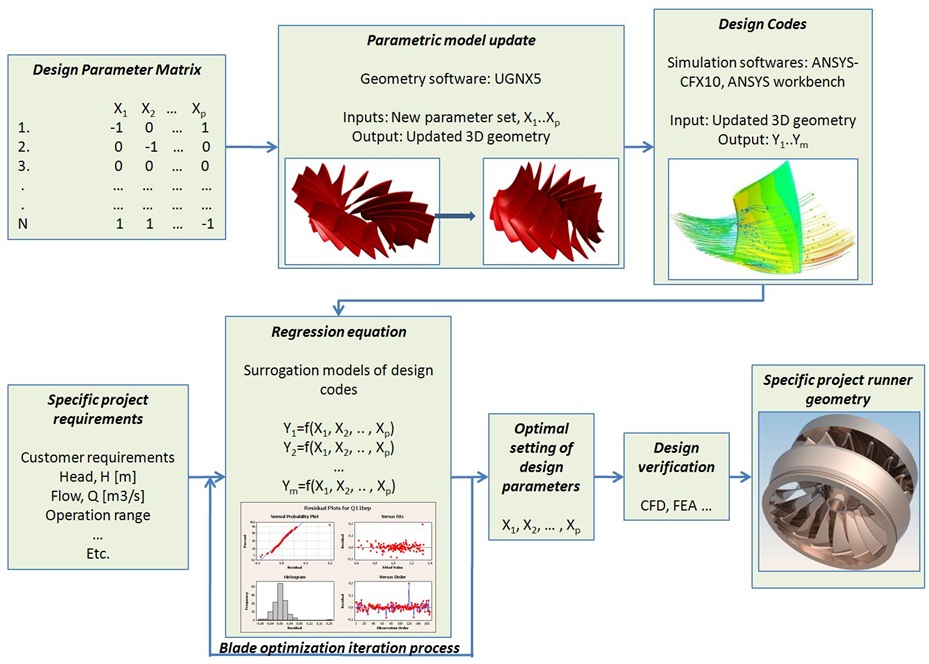
Figure 1 : Flowchart for surrogate model design method
The surrogate models can be used to give the designer insight into the relationships between design parameters and responses within the design space. It also makes it possible to evaluate a large range of responses and design parameters simultaneously, tuning the surrogate models to mimic the turbine responses in the design space. Some distinction can be made between the previously mentioned approaches and the surrogate model approach:
- The approaches mentioned above seek a global optimum. Once the optimum is found, the intermediate designs used on the process are normally discarded. In the surrogate model approach, however, the runner profiles are stored in a structured database, enabling construction of the surrogate models covering the responses in the design space.
- In the surrogate model approach, one is not only interested in finding the optimal parameter vector, but also to gain insight into the parameter and response sensitivity of the turbine design. Information about the response sensitivity is important to ensure the selection of robust runner profiles.
- When a sound surrogate model is established, it could fully or partly replace expensive and time-demanding CFD and FEM simulations in specific turbine design developments, to provide a faster and more effective exploration of the design and solution space. Further optimization can still occur as a post-processing step.
- The objective function used in the surrogate model approach, typically reflecting the customer and the turbine designer’s voice, can then change from project to project, without implying heavy project-specific simulations. This is especially important in the development of profiles for small hydro installations, where extensive project specific simulations are typically more difficult to justify economically.
- The surrogate model developments run independently of the specific project execution. The simulation codes can thus run continuously, systematically improving the surrogate models. The surrogate model complexity and actual design space covered will gradually evolve as more simulation results are added in the mission of continuously searching for improved runner profiles.
Initial considerations
To ensure a successful implementation of the surrogate model approach, careful considerations of the following factors are necessary:
- The number of parameters to solve: The computational cost of an optimization problem is greatly influenced by the number of design parameters. Hence, there is much to gain in reducing the number of relevant design parameters to the minimum appropriate. A high parameter number may increase the shape manipulation complexity, while a low number may provide a poor and a limited range of feasible solutions.
- Complexity and sample selection of surrogate model to apply: The surrogate model approach is sound as long as the model can estimate the design code sufficiently. Initial knowledge about the complexity and behaviour of each response is necessary for a successful implementation.
- Range for all design parameters defining the design space limits: Based on the previous points, the ranges for all design parameters need to be established, which when combined define the design space limits.
Geometric parameterization
Based on the considerations in the previous section, a significant effort was necessary to develop an efficient runner geometry parameterization with a minimum number of design parameters, as well as design space constraints. Functional dependencies between the design parameters were used to reduce the total number of design parameters. Classical theory [Brekke, 199910; Lepach, 200611] was used to constrain design parameters, and thereby to limit the design space. The UGNX5 parametric environment was used to generate the parametric geometry. Based on these considerations, including extensive testing for flexibility and robustness, a parametric blade defined by 10 free design parameters was developed.
Three types of design parameters were defined:
- the free design parameters which were to be systematically investigated and optimized during the optimization process;
- the dependent design parameters which were functionally dependent on one or more of the free design parameters; and,
- the fixed design parameters which were kept constant during the optimization.
One of the free design parameters was the speed number, Ω*, enabling the blade shape to change continuously with the speed number. From this parameter, several dependent parameters are defined, for example parameters that define the shroud and hub contours. Some of the other free parameters were blade inlet and outlet angles and blade lean, which are systematically and simultaneously changed during the structured design of experiment (DOE). A summary of the design parameters is given in the Table.
Table 1 : Summary or design parameters for the parametric blade
|
Design parameters = 93 |
|||
|
Free parameters to optimize |
Dependent parameters |
Fixed parameters |
|
| Blade shape |
10 |
31 |
5 |
| Blade thickness distribution |
10 |
10 |
|
| Blade inlet/outlet profiling |
4 |
8 |
|
| Shroud/hub contours |
11 |
4 |
|
| Total= |
10 |
56 |
27 |
The design space was thus populated with a relatively large range of runner designs, covering from speed number 0.3 to 0.9 where all free design parameters were changed systematically. Examples of blades based on this definition can be seen in Fig. 2.
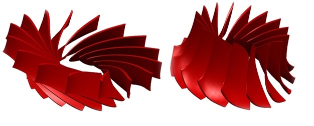
Figure 2: Flexibility and robustness: A number of 10 free design parameters were found sufficient to describe a large range of blade shapes. Speed number Ω*=0.3 to the left. Speed number Ω*=0.9 to the right.
Sample selection
A design space defined by 10 parameters that are changed in 3 levels would imply approx. 59.000 runner designs to cover all parameter combinations. This would take several years of computational effort with the current computational force and fully 3D Navier-Stokes solvers. Based on expected complexity of the responses a Box-Behnken design with 10 degrees of freedom was chosen to statistically populate the design space with a structured set of data points. 170 different runner designs were necessary to construct the surrogate models. The second-order response surface model for k input variables can be stated as
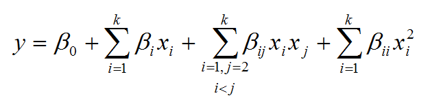
Where y is the response variable, xi, are the design parameters, andb’s are the coefficients to be estimated.
Computer analysis
A hybrid mesh from ANSYS-Icem was selected for the simulations, in view of its ability to make associative meshes for the relatively large range of geometries. A structured mesh is recognized as more accurate; however, they are more difficult to obtain for such large geometric variance of geometries, and control parameters are necessary. The mesh used (see Fig. 3) had approximately 1.4 million elements.
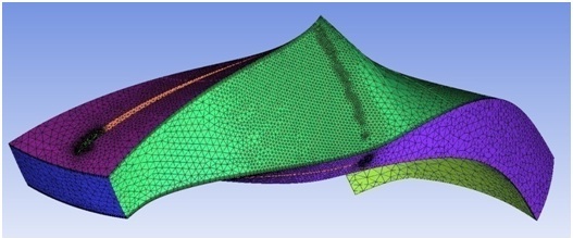
Figure 3 : Hybrid mesh used in the runner domain. 30<y+<400
A 3D Navier-Stokes solver from ANSYS-CFX 10 was used for all CFD simulations, to ensure high accuracy surrogate models. The FEM analysis was carried out in ANSYS-Workbench, using tetrahedrons elements. The final mesh size, as can be seen in Fig. 4, included about 60 000 elements. Sensitive areas were made with a higher mesh density.
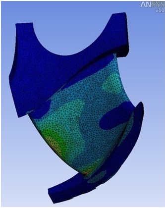
Figure 4 : Finite element mesh used for stress calculations
The performance of each design was estimated by running CFD and FEM simulations at various operating points. The following responses were extracted: runner efficiency, cavitation margins at the leading and trailing edge, best point of operation (in head and flow), operating stresses and velocity distributions downstream of the runner.
Surrogate model fitting
Minitab v15 statistical software was used to fit the surrogate models to the responses generated by the design codes. Residual analyses were carried out to identify the soundness of the surrogate models. As can be seen from Fig. 5, the surrogate model used for the prediction of efficiency at best point of operation reached a prediction standard deviation of s = 0.1 per cent compared with the level actually simulated by the design code. In the pareto-front chart shown to the left in the Figure, the actual range of best efficiencies for the different blade geometries can be visualized.
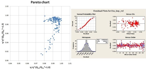
Figure 5 : To the left: A pareto-front chart showing relative efficiencies at best point of operation vs. relative efficiency at 20% higher flow. To the right: Analysis of best efficiency predicted from surrogate model predicted vs. design code prediction
In Fig. 6, the same analysis is shown on the surrogate models used for best point of operation prediction, both in head and flow. As can be seen from the Figure, prediction of best point of operation has a standard deviation on s= 0.5 per cent on head and s= 1.5 per cent on flow compared with the design code.
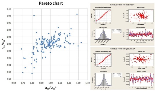
Figure 6 : To the left: A pareto-front chart showing best operating flow vs. best operating head for various turbine blades geometries. The values are normalized with the theoretical calculated value. To the right: Analysis of best operating flow (lower graph) and head (upper graph) predicted from surrogate model vs. design code prediction
Similar analyses were carried out for all involved responses, resulting into a set of surrogate model definitions. In total, about 12 000 values were extracted to establish the complete set of surrogate models.
Objective function definition
There is no unique definition of an optimum turbine design. It will be a result of the design engineer’s philosophy, which is a combination of a set of requirements (such as acceptable operating stress levels) and emphasized responses of the design (for example, weighing of efficiency at different operating points). Single-criteria definitions were defined for all responses, consisting of acceptable limits in addition to weighing factors, indicating how the different responses should mutually be emphasized. The single-criteria desirability functions are shown as d-values in Fig. 7. An overall multi-criteria objective function, denoted as composite desirability, was then defined. The composite desirability function, D, is a measure of how well the design parameter settings have satisfied the combined goal for all the responses. The overall composite function has a range of zero to one. One represents the ideal case and zero indicates that one or more responses are outside their acceptable limits. The graphical representation of the design evaluation can be seen in Fig. 7. Only few sections of the surrogate models are shown in the Figure.
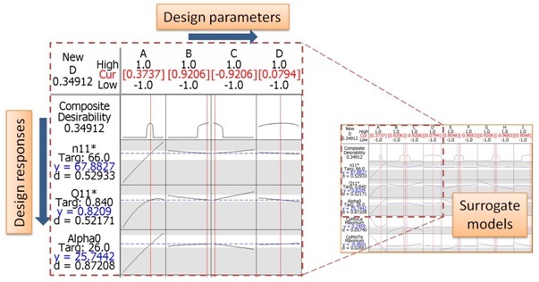
Figure 7 : Graphical presentation of surrogate models, showing the design parameters (in coded values) horizontally and responses vertically. Grey areas indicate that the actual response is outside required limits. The composite desirability, D, is shown in the upper left corner
The composite desirability function method offers an objective, systematic and efficient design space exploration. The implementation of the composite desirability function was also seen as a necessary step to consume the extensive amount of information generated by the design codes.
Validation
The methodology has shown the capability of selecting runner profiles based on a multi-objective criterion, and has already been tested versus the design code in several Francis turbine runner selections for specific projects. In Fig. 8, a comparison between surrogate models and CFD simulations for specific projects are shown.
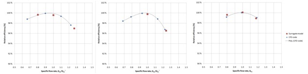
Figure 8 : Comparison of efficiencies estimated by the surrogate model vs. CFD code results in specific projects. To the left: Speed number Ω*=0.42. In the middle: Speed number Ω*=0.51. To the right: Speed number Ω*=0.71.
As can be seen from Fig. 8, the surrogate model for runner efficiency predicts the actual efficiencies calculated by the CFD code with good accuracy. The main source of the deviations observed is expected to be related to the fact that the surrogate models cover a relatively large design space compared with its limited complexity. It is expected that a revision of the design space boundaries, concentrating on the most feasible parts of the design space, will further improve the prediction accuracy.
Conclusions
A new methodology for Francis runner design has been presented. The surrogate model approach for design of Francis runners is being implemented at Spetals Verk.
The introduction of surrogate modelling in the Francis turbine design process has given a better insight into the relationships between design parameters and the various responses. A faster and more effective exploration of the design and solution space has been experienced. Selection of a new turbine blade profile for a specific project is now carried out within few minutes. The previous method would take several days of design-work. CFD and FEM simulations will now, in normal cases, only be performed to verify the design selected by the surrogate model methodology.
A Francis turbine runner design series is under development based on the surrogate model approach, resulting into a continuous and systematic philosophy. Compared with previous technology, the new technology offers clear advantages, since it offers runner designs to the specific project taking into account a much broader range of feasible runner design solutions.
The surrogate models described in this paper represent our ‘first shot’. Future steps will be both to expand the design space, and to improve further the surrogate model fit to the design codes. Spetals Verk will continue to use this methodology to take into account information from the complete design space in its turbine blade selection process for all projects. It is hoped that the method will also lead to new and improved runner profiles in the future.
Acknowledgments
The authors will like to use the opportunity to thank “Inovasjon Norge“and “Skattefunn” for their funding to our development project. Their support to our new technical development is very much appreciated.
References
1. Optimization of Hydraulic Machinery Bladings by Multilevel CFD techniques. Thum, Susanne and Schilling, Rudolf. Munich : International Journal of Rotating Machinery 2005:2, 161-167, 2005.
2. Automatic shape optimization of hydro turbine components based on CFD. Eisingher, R. and Ruprecht, A. Stuttgart : Institute of Fluid Mechanics and Hydraulic Machinery, Univarity of Stuttgart.
3. Multicriteria optimisation: Viscous fluid analysis – mechanical analysis. Mazzouji, Farid et. al. Stockholm : 22nd IAHR Symphosium on Hydraulic Machinery and Systems, 2004.
4. Design optimization of a Francis turbine runner using multi-objective genetic algorithm. Nomoto, Yasuyuki et al. Stockholm : 22nd IAHR Symphosium on Hydraulic Machinery and Systems, 2004.
5. Automated design of a Francis turbine runner using global optimization algorithms. Tomas, Laurent. Lausanne : Proceesings of the XXIst IAHR Symphosium on Hydraulic Machinery and Systems, 2002.
6. Lopèz, Lluis Ferrando. Optimum design procedure for hydraulic turbines. Lausanne : Prèsentèe a la facultè sti du gènie mècanique – Ècole polytechnique fèdèrale de Lausanne, 2005.
7. Marjavaara, B. Daniel. CFD Driven Optimization of Hydraulic Turbine Draft Tubes using Surrogate Models. Luleå : Luleå University of Technlogy. Department of Applied Physics and Mechanical Engineering Division of Fluid Dynamics, 2006. ISSN:1402-1544. ISRN: LTU-DT–06/41-SE.
8. Guinta, Anthony A. Aircraft multidisciplinary design optimization using design of experiments theory and response surface modeling methods. Blacksburg, Virgina : Virginia Polytechnic Institute and State University, 1997.
9. Qian, Cheng and Yuan, Charles. An intergrated process of CFD analysis and design optimization with Underhood Thermal Application. s.l. : Society of Automotive Engineers, Inc., 2001.
10. Brekke, Hermod. Pumper og turbiner. Trondheim : NTNU, 1999.
11. Lepach, Thomas. Entwurf and Optimierung von Francis Turbinen. München : Technische Universität München, Institut für Energietechnik, 2006.